The amplifier valve test process:
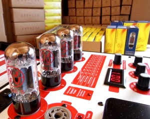
We do our utmost to ensure your valves reach you in perfect working order, from the moment we receive them direct from the manufacturer to the time of dispatch. All our valves (preamp, power-amp & rectifier) are thoroughly tested at the factory before being shipped to our repair centre. Tests include: measurement of internal vacuum level, cathode emission capability, filament voltage and current, anode current saturation level, valve leakage, noise & microphonic levels. We then thoroughly test them pre-dispatch using professional test equipment by B&K & Maximatcher (US). We carefully match our graded* power valves using a digital calibrated tester (see below). Preamp valves are tested for V1 (phase splitter/inverter) position suitability & stocked accordingly. *Note: All power valves come to us graded by the manufacturer (factory grading refers to a general lower-tolerance matching system used in mass valve production)
The importance of matching power valves:
In a valve power amplifier, the output stage normally operates on a push-pull configuration. Certain amplifiers use valves in a parallel arrangement for more output, however the design is still based on the push pull theory. In this commonly used design, the power valves work together in a balanced fashion. It is crucial the valves are matched, as ideally each valve should handle the same amount of load/work in the circuit. If the dynamics of the valves are not correctly balanced poor sound quality can result along with overheating & the valves lifespan can often be significantly reduced.
Many amplifiers are designed to use power valves that have similar cathode current. Valves produced at the same time will have variations in their cathode current, this is why testing and matching is required.
How we match our power valves:
Before matching, we burn-in the power valves by applying a high voltage across the plate and screen. We do not damage the valves in any way during the burn-in process & it does not affect the valves lifespan, but it helps us detect any poor performing valves. Any valves that fail during the burn-in process are rejected. All our power valves are matched based on plate current (IP) which is considered to be the most accurate method. We also check for transconductance (GM) test results, correct heater operation & inter-electrode short circuits. Matched power valve sets with the same (Ip) values are essential in a valve amplifier & help maintain an accurate frequency response whilst minimising distortion. Basically output valves that are matched perform better & last longer! We match our power valves to be within 5% of measured plate current (Ip). Obviously test results can vary slightly between valve types & manufacturers, but generally these tolerances are achievable give or take 2 or 3 percent.
Preamp valve testing:
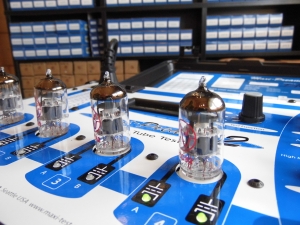
We use a precision digital measurement station for testing our preamp valves. Dual triodes and other signal tubes are tested for the electrical characteristics of gain (A), transconductance (Gm) and noise (dBm). During this test process, balanced triodes are selected & stocked ready for use in phase splitter/inverter positions. Unlike many retailers we do not charge extra for this service.
The phase splitter/inverter:
In an all-valve amplifier the phase splitter or inverter will be a (dual triode) preamp valve with balanced triodes, usually an ECC83 (12AX7) or ECC81 (12AT7). The function of this valve is to evenly drive both sides of the amplifiers output stage in a push pull fashion. Whilst an unbalanced triode can be used in the phase inverter position, it can reduce power & compromise the tone characteristics of the amplifier. All our amplifier kits (where required) are supplied with a balanced phase inverter triode. The phase splitter/inverter is often found last in a line of pre amp valves and usually nearest the power valves, (commonly furthest away from the input jack).
Other valve tests:
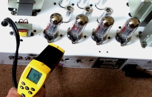
After the installation of new valves during servicing & repairs, we carry out further specific tests under load conditions. The amplifier is checked for correct operation & at this point the bias settings are adjusted, if necessary. All valves are monitored for performance & output valves checked for temperature balance & stability (pictured right).


